
Different types of logic gates – This book covers the entire syllabus of “Computer & Information Technology” prescribed by the BNMC for B.Sc. in Nursing Science & Diploma in Nursing Science & Midwifery students. We tried to accommodate the latest information and topics.
This book is an examination setup according to the teachers’ lectures and examination questions. We hope in touch with the book students’ knowledge will be upgraded and flourished. The unique way of presentation may make your reading of the book a pleasurable experience.
Different types of logic gates
Digital systems are said to be constructed by using logic gates. These gates are the
- AND,
- OR,
- NOT,
- NAND,
- NOR
- EXOR and
The basic operations are described below with the aid of truth tables.
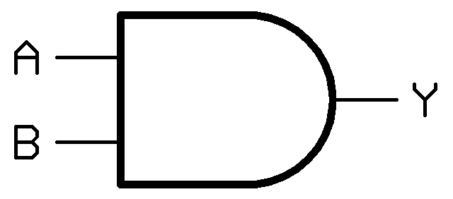
1. AND Gate
- Two or more input signals and one output signal.
- Output is high when both the inputs are high.
- Logic equation Y = A. B called as Boolean equation.
- Where A & B are the inputs and Y is the output for all standard symbols of gates shown below.
Y = AND B AND C……. N
Y = A.B.C……. N
Logic Diagram/Symbol
Truth Table
| INPUT | OUTPUT | |
| A | B | A.B |
| 0 | 0 | 0 |
| 0 | 1 | 0 |
| 0 | 1 | 0 |
| 1 | 0 | 0 |
| 1 | 1 | 1 |
2. OR Gate
- Two or more input signals and one output signal.
- Output is low when both the inputs are low.
- Logic equation Y = A + B.
Y = A OR BORC……. N
Y = A+B+C……. N
Logic diagram/Symbol

Truth Table
| INPUT | OUTPUT | |
| A | B | A.B |
| 0 | 0 | 0 |
| 0 | 1 | 1 |
| 1 | 0 | 1 |
| 1 | 1 | 1 |
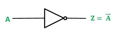
3. NOT Gate
- One input signal and one output signal, also called as inverter.
- Output is always opposite state of the input.
- Logic equation Y = A
- Where is A is the complement of A.
y = NOTA
y = A‾
Logic Diagram/Symbol
Truth Table
| INPUT | OUTPUT |
| A | A‾ |
| 0 | 1 |
| 1 | 0 |
4. NAND Gate
- Two or more input signals and one out signal.
- It has high output when at least one of the input is zero or low.
- All input signals must be high to obtain low output.
- Logic equation Y = A. B
Y = A NOT AND B NOT AND CN
Y = A NAND B NAND C……. N
Logic Diagram/Symbol

Truth Table
| INPUT | OUTPUT | |
| A | B | A.B‾ |
| 0 | 0 | 1 |
| 0 | 1 | 1 |
| 1 | 0 | 1 |
| 1 | 1 | 0 |
5. NOR Gate
- One or more input signals and one output signal.
- If one of the input is high then output is low
- Logic equation Y = A + B
Y = A NOT OR B NOT OR C…….N
Y = A NOR B NOR C…….N.
Logic Diagram/Symbol

Truth Table
| INPUT | OUTPUT | |
| A | B | A.B |
| 0 | 0 | 1 |
| 0 | 1 | 0 |
| 1 | 0 | 0 |
| 1 | 1 | 0 |
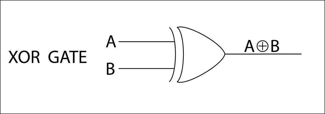
6. EXOR Gate
- Two or more input signal and one output signal.
- Output is low when both the inputs are same.
- Logic equation Y = A XOR B
Y = XOR B XORC……. N
Y = ABC……N
Logic Diagram/Symbol
Truth Table
| INPUT | OUTPUT | |
| A | B | A+B |
| 0 | 0 | 0 |
| 0 | 1 | 1 |
| 1 | 0 | 1 |
| 1 | 1 | 0 |